Analysis of LP Flash Column
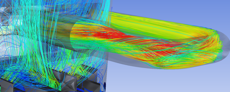
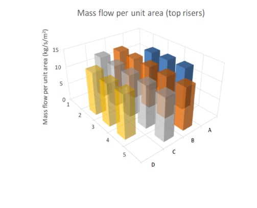
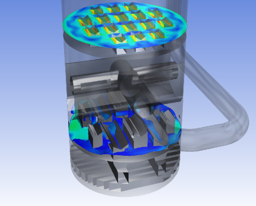
Kranji Solutions was commissioned to undertake the validation of the internals of an LP Flash column. Computational Fluid Dynamics (CFD) simulations were applied in detailed analysis of flow distribution and identifying the possible issues. The two-phase simulation revealed even gas flow through the top riser and the mesh pad, but a mal-distribution of the liquid at the bottom, which can potentially incur in operational inefficiencies.
BUSINESS PROBLEM
Revamp internals will be installed by a vendor in a LP Flash Column on a downstream gas processing facility.
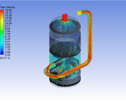
The main interest is in the upper part of the LP Flash Column, where a new T-shaped inlet distributor and a collector tray with downcomers and risers are foreseen. 20 MMSCFD of gas and 140m3/hr of liquids will flow through the upper part of the column via the new distributor, located in the flash box. An additional 100MMSCFD of gas is flowing from the bottom part of the column upwards to the downstream random packing.
Kranji Solutions was requested to conduct a Third-party Computational Fluid Dynamics (CFD) study of the unit with the internals recommended by the vendor for the revamp.
ANALYSIS
CFD Simulations and associated analysis provided the following:
- Visualisation of gas flow distribution throughout the upper part of the LP Flash Column
- Liquid flow distribution through the downcomers
- Gas (and liquid) flow through the risers
- Droplet tracking of liquid (DPM), with liquid load evaluation towards the random packing
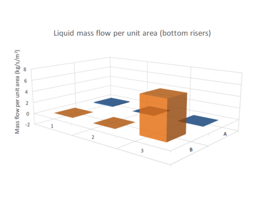
Computational Fluid Dynamics indicated unexpected liquid flow distribution near the collection tray.
CONCLUSION
The assessment determined that the gas flow within the column achieved an acceptable uniform flow distribution. Nevertheless, a less favorable liquid flow behavior is observed:
- Unexpected liquid flow through the gas risers
- Uneven liquid flow distribution through the downcomers
Hence, further analysis and modifications to the revamp internals, such as adding perforated baffles, will be required, to improve the liquid distribution near the collector tray.
SUMMARY
Expert application of CFD modelling revealed successful gas distribution but highlighted issues with liquid distribution. While the gas flow achieved uniformity across the vessel, the liquid phase exhibited maldistribution at the bottom risers and downcomers.
